
Directions for Use
Replacing Circuits and Pads:
Step 1.
Remove the defective pad, land or conductor. If there is a connecting circuit on the circuit board surface, you can apply liquid flux and tin it with solder.
If the base material is severely damaged it may have to first be repaired using epoxy.
For more information see Circuit Bond Kit and Base Board Repair Kit.
Step 2.
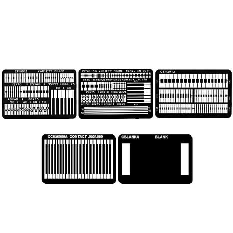
Select a replacement pad, land or conductor from a Circuit Frame and carefully scrape off the adhesive film from the solder joint area. Then trim it out from the Circuit Frame.
Step 3.
Place the new pad, land or conductor in position using high temperature tape. Apply heat to the tape for 5 seconds using a Bonding Iron or Bonding System. The heat transmits through the tape to quickly tack the pad, land or conductor in place.
Step 4.
Remove the high temperature tape and again apply heat using the Bonding Iron or Bonding System, but this time directly to the top surface of the pad, land or conductor. Apply light pressure to permanently cure the adhesive. The bonding time to cure the dry-film adhesive is only 30 seconds.
To complete the procedure, if the new pad, land or conductor has a connecting circuit, apply liquid flux and then lap solder the connection.
Other Information
 |
Our Technology Guides page has links to our comprehensive PCB Rework & Repair Guide |
All Downloads
| Filename | Size | Download |
| PCB Rework and Repair Guide | 6.79MB |